
From Pitch to Plating: How to Precisely Select Pin Header Specifications for Your Application
In the world of electronic hardware design and PCB layout, the Pin Header is often dubbed the "Lego brick" of the circuit board. While its structure appears simple—metal pins secured in an insulating plastic base—improper selection can lead to assembly difficulties, signal interference, or even system failure due to poor contact. In today's landscape of high integration and automated production, precise selection of pin header specifications has become a critical pillar for product reliability.
This article delves into four key dimensions—Pitch, Mounting Style, Plating Process, and Structural Keying—to guide you through selecting the specifications that best align with industrial standards and commercial requirements.
I. Pitch: The Core of PCB Layout and Mechanical Strength
The pitch is the most intuitive and fundamental parameter of a pin header, directly impacting the Routing Density of the PCB. Selection requires a balance between space-saving and mechanical durability.
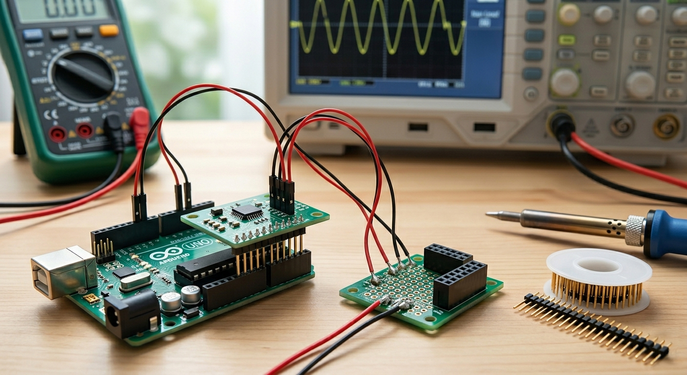
- 2.54mm (0.1 inch): The Classic Industrial Standard The most ubiquitous specification, offering excellent durability and ease of manual soldering or breadboard testing (e.g., Arduino). Ideal for industrial equipment, large appliances, and prototyping, with a typical current capacity of up to 3A.
- 2.0mm: The Modern Mainstream Balance Now a staple in smartphones and server motherboards, 2.0mm pitch offers a perfect equilibrium between structural integrity and reduced PCB footprint. It is the preferred choice for internal communication modules.
- 1.27mm / 1.0mm: Precision for Compact Electronics Designed for wearables, IoT sensors, and high-density IC designs. These fine-pitch pins are fragile and not recommended for frequent mating. They also demand high precision in Solder Paste (Reflow Soldering) volume control.
II. Mounting Style: DIP vs. SMT Logic
The mounting method depends on production volume, physical stress requirements, and PCB space planning.
■ Features: Pins penetrate the PCB through-holes. This provides superior physical anchoring, capable of withstanding significant mating forces and mechanical stress.
■ Applications: External power interfaces, maintenance interfaces requiring frequent swaps, or high-vibration environments.
■ Surface Mount (SMT):
■ Features: Soldered directly onto the surface of the PCB copper foil. This saves routing space on the opposite side of the board and is ideal for high-speed Pick-and-Place automation.
■ Applications: Slim consumer electronics and high-density mass-produced products.
■ Right Angle (Side Entry):
■ Features: Pins are bent at 90 degrees. Ideal for side-to-side PCB docking or height-constrained environments, while also optimizing airflow paths for cooling.
III. Plating Process: The "Golden Rule" for Longevity
Plating prevents the base material (such as brass or phosphor bronze) from oxidizing and ensures low Contact Resistance and good solderability.
-
Full Gold (Gold Flash): Offers the highest corrosion and oxidation resistance. In humid or corrosive industrial environments, gold plating guarantees hundreds of mating cycles. Common in aerospace, medical, and military-grade precision instruments.
-
Full Tin: Highly cost-effective but prone to oxidation layers over time. Frequent mating can lead to "fretting corrosion," resulting in poor contact. Primarily used in low-cost, disposable consumer electronics or toys.
-
Selective Gold (Duplex Plating): The industry's most cost-effective mainstream choice. It uses gold plating on the mating area for signal stability and tin plating on the solder tail to optimize solder wetting.
IV. Structure and Keying: Enhancing Assembly Efficiency
In complex systems, structural design can effectively reduce human error during assembly.
-
Pin Header Strip: Bare pins that are lightweight and low cost but lack orientation guidance. It is recommended to clearly mark Pin 1 on the PCB silkscreen.
-
Box Header / Shrouded Header: Features a plastic "fence" and a notch for Keying (Polarization). When used with notched ribbon cables, it ensures 100% correct orientation and provides physical protection for the pins against bending.
Technical Q&A: Addressing Hardware Development Pain Points
Q1: How do I evaluate the rated current? What happens if it's exceeded?
A: Current capacity depends on the pin material and cross-sectional area. Generally, 2.54mm headers support ~3A, while 1.27mm should stay under 1A. Exceeding the rating causes a rapid heat increase at contact points, potentially melting the plastic base or causing thermal fatigue in solder joints.
Q2: How do I prevent "floating" or tilting during SMT?
A: This is usually related to pad design and solder paste volume. We recommend choosing SMT specs with Locating Pegs (Bosses) and using specialized Pick and Place Caps (Vacuum Caps) to ensure the machine nozzle can place the component precisely.
Q3: How does humidity affect selection?
A: For equipment in high-humidity or salt-spray environments (e.g., coastal facilities), you must use a thick gold plating (30u" or higher). Tin-plated headers in these environments will rapidly develop "Tin Whiskers" or oxidation films, leading to signal failure.
V. Quick Selection Checklist
Before finalizing your PCB Layout, confirm the following:
-
Current Load: Does the single-pin current have a 20% safety margin?
-
Clearance Height: Will the insulator height interfere with the enclosure or other components?
-
Soldering Standards: Does it meet Lead-Free (RoHS) high-temperature requirements?
-
Certification: Does it require UL or Halogen-Free compliance?