
 The internal and external connectivity of power banks revolves around power input/output, battery management, and internal circuit integration. As technology evolves, the specifications for connectors and wiring have become increasingly sophisticated.
Here is the English translation of the common connectors and wiring classifications found in power banks:
1. External I/O Connectors
These are the interfaces users interact with most frequently, responsible for charging the power bank itself and powering external devices.
■ Lightning (Rare): Some brands include a Lightning input port to allow iPhone users to use a single cable for bidirectional charging.
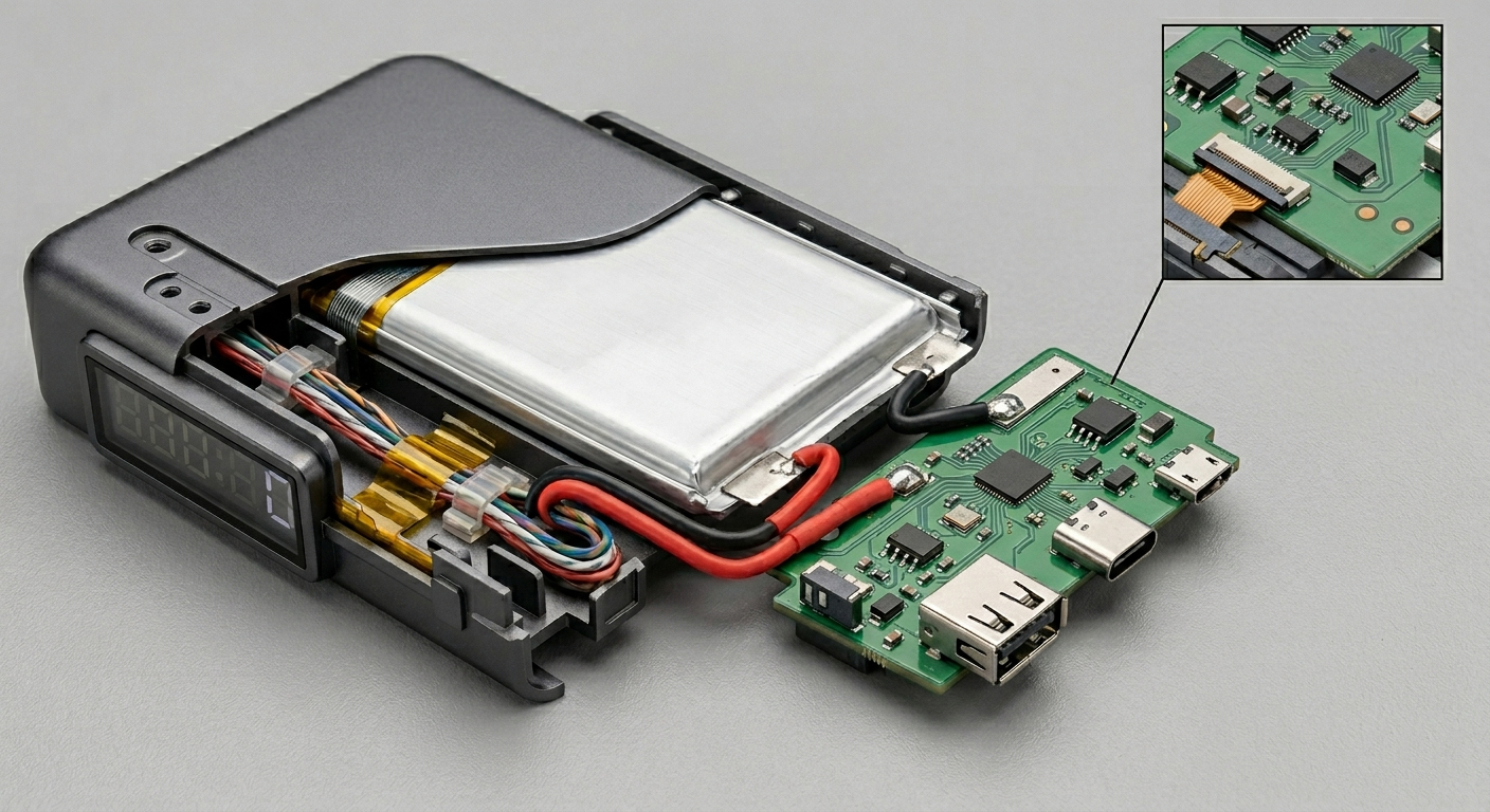
2. Internal Wiring & Interconnects
Internal circuitry must handle high currents while accounting for heat dissipation and spatial constraints.
■ Battery Leads: Typically use UL-standard electronic wires (such as AWG 20-26). These connect the battery cells (18650 or Lithium-polymer) to the PCB motherboard. For safety, these wires require high temperature resistance and superior insulation.
■ FPC/FFC (Flexible Printed Circuit / Flat Flexible Cable): In ultra-slim power banks, FPC is used instead of traditional wires to connect the motherboard to LED indicators, buttons, or wireless charging coils.
■ Nickel Strips: When connecting multiple cells in series or parallel, nickel strips are used via spot welding. They are preferred for their low resistance and high conductivity.
3. Charging Cables
Whether included or user-provided, the cable specification dictates the overall charging efficiency.
■ Type-C to Type-C Cables: To achieve high-power output (e.g., 60W or 100W), the cable must contain an E-Marker chip.
■ Multi-functional (All-in-One) Cables: Many power banks with "built-in cables" integrate USB-C, Lightning, and Micro-USB. The design of these cables must prioritize fatigue resistance to withstand frequent bending.
4. Key Technical Specifications
When selecting or designing these connection components, the industry focuses on the following benchmarks:
| Component | Key Technical Indicators |
| Connectors | Mating Cycles, Contact Resistance, Oxidation Resistance (Gold/Nickel plating) |
| Internal Wiring | Flame Retardant Rating (UL94V-0), Ampacity (Current Load Capacity), Impedance Matching |
| PCB Interface | SMT Solder Strength, Structural Stability (Side-mount or Vertical-mount) |