
The LEGOs of Electronics: Pin and Female Headers Make Complex Soldering a Thing of the Past
In the early stages of electronic product development and prototyping, time and flexibility are the deciding factors between a project's success and failure. If every circuit module required permanent hard-wiring, the development process would become highly inefficient, leaving an exceptionally low margin for error.
Why Do Electronic Engineers Prefer Pin Header Connectors?
The combination of a pin header and a female header revolutionizes the development workflow by providing a detachable electrical bridge. This modular interconnect solution not only optimizes the hardware layout but also makes complex circuit development as intuitive as building with toy blocks.
1. Establishing a "Modular" Stacked Architecture
During the initial phases of development, engineers rarely design a flawless, all-in-one printed circuit board (PCB) on the first try. By utilizing pin and female headers, functionalities can be decoupled into distinct parts:
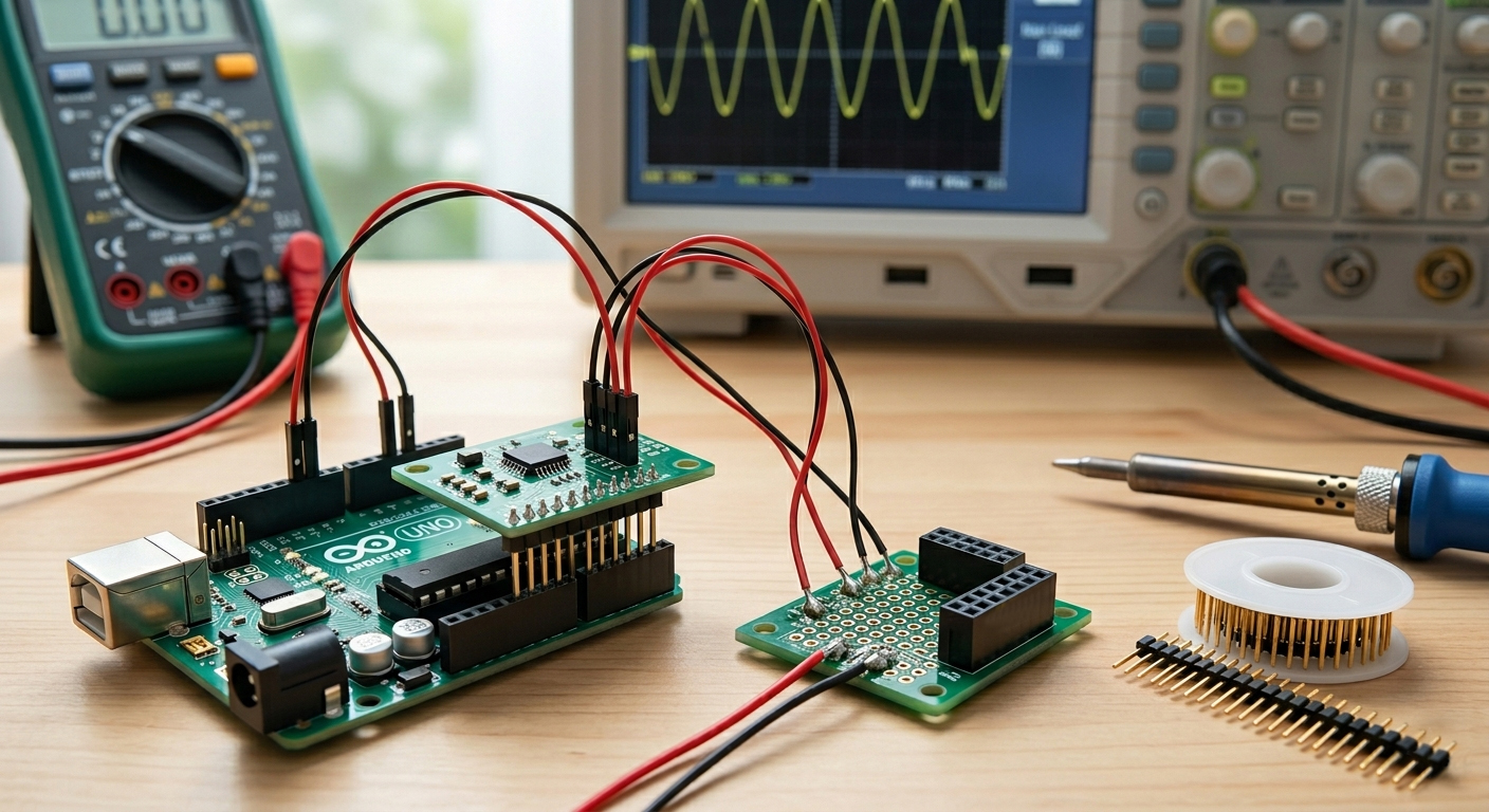
■ Motherboards and Expansion Boards: Taking platforms like Arduino or Raspberry Pi as examples, the mainboard is typically soldered with female headers, while functional modules (such as sensors and motor drivers) are populated with pin headers.
■ LEGO-Style Assembly: This sandwich-like stacked structure allows developers to swap out different functional modules at any time—just like playing with LEGO bricks—without needing a soldering iron. This multi-layer circuit stacking technology has become the standard practice in modern electronic prototyping.
2. Streamlining Testing and Debugging
Where soldering is permanent, headers are temporary. This distinction delivers a massive advantage during the debugging phase:
■ Effortless Signal Measurement: Because the pins of a header are directly exposed, the probes of an oscilloscope or multimeter can easily clip onto them for signal acquisition. This eliminates the tedious need to hunt for microscopic test points on the PCB.
■ Rapid Fault Isolation: If a specific module is suspected of being faulty, you can simply unplug the pin header and swap in a fresh module. Conversely, with hard-wired connections, the thermal stress introduced by a high-temperature soldering iron during desoldering risks damaging nearby delicate electronic components.
3. Resolving the Conflict Between Prototyping Costs and Iterative Changes
Redesigning and ordering new PCB spins (tape-outs) is both time-consuming and expensive. Leveraging headers effectively lowers the cost of prototype development:
■ Jumper Settings: By pairing pin headers with jumper caps, developers can reconfigure circuit paths on the same PCB on the fly (e.g., toggling between 3.3V and 5V power rails). This is critically important for early-stage logic verification.
■ Breadboard Friendly: Modules populated with pin headers can be plugged straight into a breadboard and connected to other components via DuPont wires. This non-destructive experimentation workflow allows engineers to hold off on final soldering until the circuit layout is fully verified.
4. Key Comparison: Header Connections vs. Direct Soldering
When choosing the interconnection method for electronic components, developers must weigh physical properties against electrical characteristics:
|
Characteristic |
Header & Female Header Connection |
Direct Soldering (Hard-Wired) |
|
Flexibility |
Extremely high; allows hot-swapping and easy replacement. |
Extremely low; requires desoldering to make changes. |
|
Development Speed |
Fast; ideal for rapid iterative verification. |
Slow; requires a soldering iron for every modification. |
|
Mechanical Strength |
Moderate; not suitable for high-frequency, severe vibration. |
Extremely high; offers a structurally robust joint. |
|
Space Consumption |
Large footprint; requires vertical clearance for the plastic insulator body. |
Minimal; adds virtually no extra height or volume. |
|
Contact Resistance |
Slightly higher; heavily dependent on plating quality. |
Lowest possible; achieved through molecular metal fusion. |
5. Emerging Trends in Early-Stage Development
As technology evolves, pin and female headers continue to advance into new forms that displace traditional soldering and boost Electronic Design Automation (EDA) efficiency:
■ Press-fit Pins: These pins are forced into PCB through-holes using mechanical pressure alone, completely eliminating the need for thermal heating. They retain the convenience of standard headers while delivering mechanical stability that rivals a soldered joint.
■ Polarized (Keyed) Structures: To prevent accidental reverse insertion during the development phase—which can lead to catastrophic board burnouts—modern designs frequently employ shrouded headers (box headers) to guarantee absolute polarity correctness.
6. Expert Q&A: Optimizing Circuit Header Applications
To help both beginners and veteran engineers quickly master these components, we have compiled the most frequently asked questions regarding circuit connector optimization:
Q1: Why do Arduino shields mostly use stacked pin headers instead of ribbon cables?
A: Stacking layouts maximize the utilization of vertical space, and pin headers provide excellent mechanical support. Compared to ribbon cables, pin headers exhibit lower contact resistance, making them better suited for high-frequency data transmission and low-power delivery.
Q2: How do I select high-quality pin and female headers?
A: The secret lies in the plating. For critical signal paths, it is highly recommended to use gold-plated headers to effectively prevent oxidation and minimize contact resistance. For general-purpose applications, tin-plated versions can be selected to curb costs.
Q3: Are pin header connections reliable in high-vibration environments?
A: If your project faces intense vibration (such as in drones or automotive equipment), standard friction-fit pin headers may back out and loosen over time. In these scenarios, it is best to secure the boards with mechanical standoffs and screws, or transition to latched connectors / direct soldering after prototype verification.
Q4: Compared to direct soldering, is the signal transmission stable through headers?
A: For the prototyping phase, the electrical connection provided by headers is more than stable enough. However, in high-frequency signal or ultra-high-current applications, direct soldering offers lower contact resistance and superior long-term stability. A common best practice is to use headers during early prototyping and transition to soldering or Surface Mount Technology (SMT) for mass production.
Q5: How do I choose the correct pin spacing (Pitch)?
A: The most prevalent standard pitch is 2.54mm (0.1 inch), which matches the standard spacing of most breadboards and Arduino microcontrollers. If your product has tight volumetric constraints, you can opt for miniaturized form factors like 2.0mm or 1.27mm pitches.
Q6: What is the primary difference between gold plating and tin plating on headers?
A: Gold-plated headers deliver exceptional oxidation resistance and premium electrical conductivity, making them perfect for harsh environment developments and high insertion-cycle counts. Tin-plated headers offer a budget-friendly alternative best suited for cost-sensitive or single-use prototypes.
Q7: Why should I prioritize headers over direct soldering during early prototype development?
A: The overarching reasons are flexibility and velocity. Headers allow for a detachable connection, empowering engineers to swap modules, capture signals, or isolate faulty components on the fly. This avoids frequent desoldering with a hot iron, protecting adjacent sensitive parts from thermal degradation.
Q8: How can I prevent accidentally plugging a header module in backward and frying the circuit?
A: It is highly advisable to use connectors featuring physical keying or polarized safeguards, such as shrouded box headers. These designs physically restrict the insertion direction, ensuring electrical polarities are perfectly aligned every single time.
Q9: What are "Press-fit Pins," and what advantages do they offer?
A: These are solderless pins designed to be pressed directly into PCB plated through-holes via mechanical force without thermal application. Their primary benefit is marrying the pluggable convenience of standard headers with the rugged mechanical integrity of a traditional solder joint, all while sparing heat-sensitive components from thermal shock.
Q10: Can pin header connections entirely replace direct soldering in terms of performance?
A: No, they cannot. While headers hold a massive logistical advantage during development, direct soldering remains the superior choice for mass production. Soldering guarantees lower contact resistance, superior structural integrity against shock and vibration, and a significantly smaller physical footprint. Consequently, the industry standard is to utilize headers for prototype approval and return to hard-wiring or SMT in final production to achieve optimal cost-efficiency and space utilization.