
Understanding Terminal Block Classification in 3 Minutes: A Complete Analysis of Mounting Methods, Wiring Technologies, and Functional Characteristics
In the fields of industrial automation, power distribution, and electronics manufacturing, the terminal block is highly regarded as the bridge of electrical circuits. Although it appears deceptively simple, selecting the right type of terminal block directly determines the stability and maintenance efficiency of the entire electrical control system—especially in extreme environments characterized by high vibration, high voltage, or limited space.
To help engineers and procurement professionals optimize their wiring workflows, this article provides a comprehensive overview of terminal block classification across three major dimensions: mounting methods, wiring technologies, and functional characteristics.
1. Classification by Mounting Method: The Foundation of Space Configuration and Enclosure Design
The mounting method of a terminal block must align with the equipment's enclosure design and overall space planning. This has a direct impact on the convenience of subsequent maintenance.
-
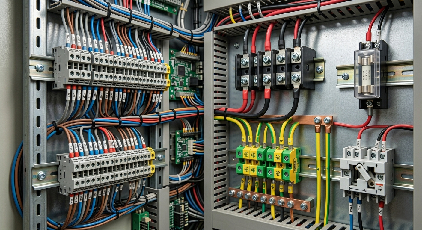
DIN Rail Mount (European Style): This is the standard configuration for industrial automation control panels. Its primary advantage lies in standardization; it can be quickly snapped onto 35mm guide rails (such as TS35), allowing modules to be added or removed at any time based on circuit requirements. In large-scale industrial distribution boards, rail-mounted terminal blocks serve as the core of modular design.
-
PCB Mount (Printed Circuit Board): These are soldered directly onto printed circuit boards. As electronic devices become increasingly miniaturized, PCB terminal blocks have evolved to feature tighter pitches (such as 3.5mm, 5.0mm) and higher current load capacities. They are widely used in power supplies and industrial frequency inverters.
-
Pluggable: Consisting of a male plug and a female socket, this design allows for complete electrical separation without the need to disconnect individual wires when equipment requires frequent maintenance or module replacement. This significantly shortens on-site downtime and improves after-sales maintenance efficiency.
2. Evolution of Wiring Technology: Balancing Installation Efficiency and Mechanical Reliability
The wiring method (clamping structure) is the core concern for field engineers, as it directly affects installation speed, contact resistance, and safety in high-vibration environments.
-
Screw Connection: This is the most classic wiring technology. By tightening a screw to apply pressure via a clamping plate onto the wire, it delivers excellent contact pressure and low resistance. However, its disadvantage is that it can loosen over time in high-vibration environments (such as vehicles or heavy construction machinery), typically requiring regular inspections and retightening.
-
Spring Cage Connection: This method utilizes a constant-pressure spring clamp to automatically lock the wire in place. It offers exceptional anti-vibration performance and highly consistent wiring quality, as it eliminates variations caused by differing manual tightening forces among workers. It is the preferred choice for railway transportation and wind power equipment.
-
Push-in Technology: This is the mainstream technology of the Industry 4.0 era. Solid wires or stranded wires with ferrules can be inserted directly without tools, boosting wiring efficiency by more than 50% compared to traditional screw connections. For large-scale automation production line wiring, this significantly reduces labor costs.
3. Classification by Functional Characteristics: Meeting Specific Circuit Protection Needs
Beyond basic electrical conductivity, modern terminal blocks also play vital roles as "circuit protectors" and "signal distributors."
|
Function Type |
Application Scenarios |
Technical Key Points |
|---|---|---|
|
Grounding |
Safety protection and lightning surge protection |
Features a green-and-yellow housing. The internal conductor connects directly to the DIN rail, providing a discharge path for fault currents. |
|
Fuse |
Overload and short-circuit protection |
Features a built-in fuse holder to protect high-value downstream electronic components in the event of an abnormal current. |
|
Multi-level |
High-density wiring space optimization |
Increases the number of wiring layers vertically (such as double or triple levels), saving over 50% of DIN rail space. |
|
Disconnect / Test |
Circuit measurement and troubleshooting |
Interrupts current via a knife switch or plug-in disconnect, allowing signal circuit measurement without disconnecting wires. |
4. Professional Selection Checklist: Ensuring Electrical Safety and Compliance
When procuring or designing terminal blocks into a system, please ensure the following four core parameters are verified:
-
Electrical Parameters and Material Safety: The rated voltage (V) and rated current (A) must include a safety margin of at least 20%. Additionally, the housing should be made of PA66 engineering plastics that meet the UL94 V-0 flame-retardant rating to ensure safety at elevated temperatures.
-
Wire Range: Confirm that the wire gauge used on-site (AWG or mm2) falls within the permissible range of the terminal block to prevent arcing caused by poor contact.
-
Environmental Standards and International Certifications: For export trade, verify compliance with UL (American standard) or IEC (European standard). For specific industries, check for compliance with IATF 16949 (automotive) or EN 45545 (railway applications).
-
Sustainability Trends and Green Manufacturing: Compliance with RoHS/REACH environmental standards has become a basic baseline for entering global markets.
Professional Q&A: Technical Troubleshooting for Terminal Block Applications
Q1: Why is it recommended to abandon screw terminal blocks in favor of spring-cage or push-in types in high-vibration environments?
A: Screw connections rely primarily on friction to maintain clamping pressure. Prolonged vibration can cause screws to back out slightly, increasing contact resistance and potentially creating a fire hazard. In contrast, spring connections provide continuous, dynamic pressure that compensates for any displacement caused by environmental vibration, ensuring the connection remains tight at all times.
Q2: Can push-in terminal blocks accommodate stranded flexible wires?
A: Yes, they can. However, to ensure smooth insertion and optimal stability, it is highly recommended to crimp a ferrule onto the stranded wire first. If you choose not to use a ferrule, you will need to press the release button with a screwdriver before inserting the wire, which functions similarly to a standard spring-cage connection.
Q3: Do multi-level terminal blocks (such as triple-level types) suffer from heat dissipation issues?
A: High-density wiring does lead to heat accumulation. During the selection process, you should consult the manufacturer's Derating Curve. If the operating environment features high ambient temperatures and sustained full loads, it is recommended to insert end covers (partition plates) or leave small gaps at regular intervals within the terminal block array to facilitate heat dissipation.