
Electronic Connector Selection Guide: Key Characteristic Comparison Between USB Type-C Male and Female
Within the architectures of modern smartphones, intelligent automotive cockpits, industrial sensor arrays, and high-tier medical instrumentation, the USB Type-C interface has established itself as the global cross-industry standard. This dominance is driven by its robust Power Delivery (PD) limits, high-speed data bandwidth channels, and the ultimate user convenience of reversible blind-mating. However, when executing hardware engineering, Bill of Materials (BOM) optimization, and connector sourcing tracks, product development teams must clearly differentiate between the physical characteristics, mechanical constraints, and Design for Manufacturability (DFM) variations of the Male Plug versus the Female Receptacle. This comparative analysis provides a systematic blueprint to guide R&D and procurement decisions.
I. Structural and Physical Architecture Comparison: 24-Pin Configurations and Mechanical Wear Mechanics
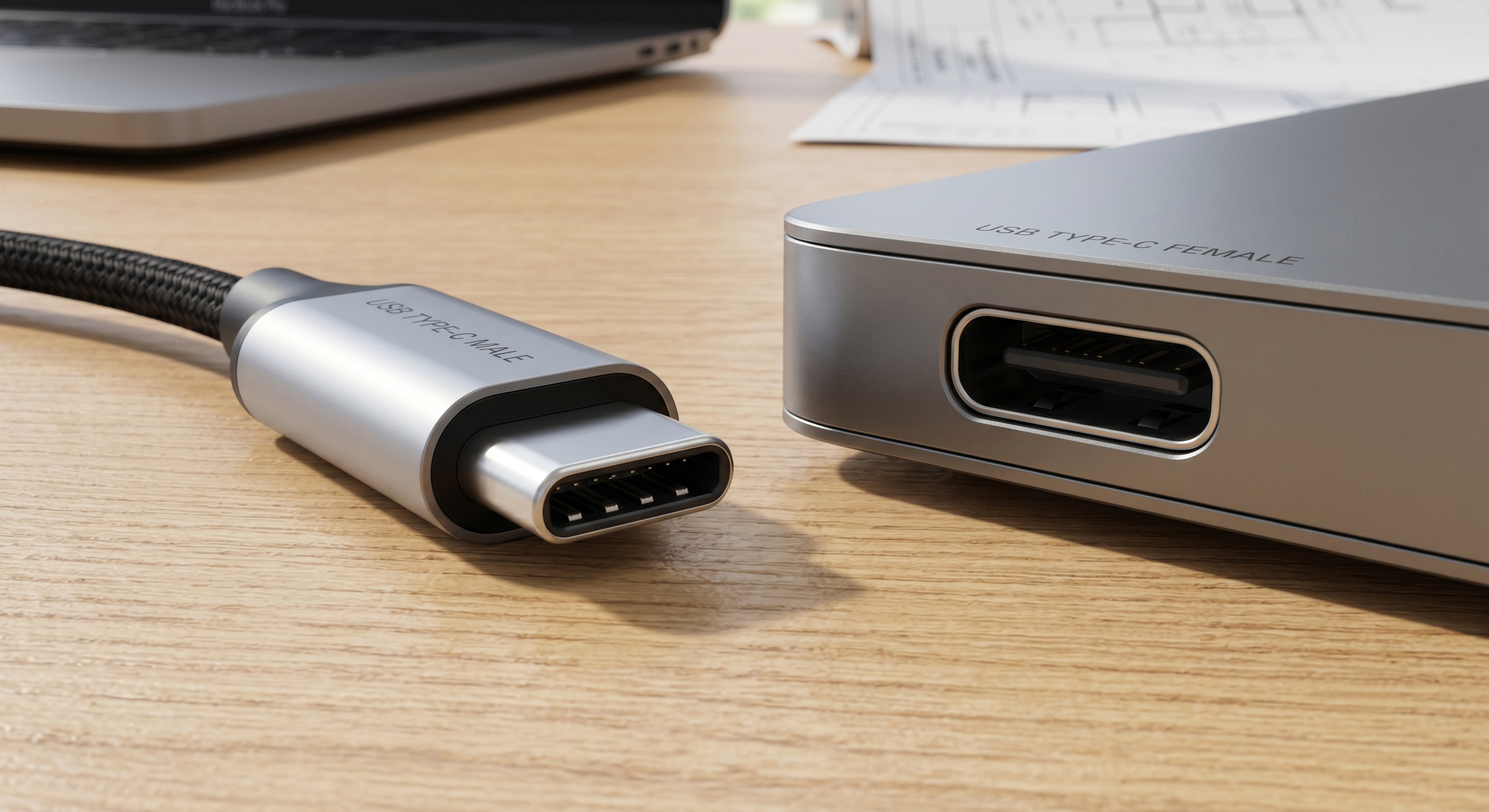
The foundational architecture of the USB Type-C standard relies on a symmetrical layout containing 24 independent electrical pins. The male plug and female receptacle exhibit a mirroring geometric relationship, which directly regulates long-term contact resistance and physical retention parameters.
(I) Mechanical Lifecycle Allocation Across Paddle Cards and Mid-Plates
- Geometric Divergences in Internal Assemblies
(1) Male Component (Plug): Typically comprises a protective outer metallic shell encasing a thin internal laminate known as a "Paddle Card," with contact traces applied symmetrically on both faces.
(2) Female Component (Receptacle): Features a rugged, multi-grounded metallic shielding chamber housing an isolated internal "Mid-plate," which arrays two rows of 12 spring-loaded terminal contacts.
- Sacrificial Wear Mechanics Safeguarding Equipment Lifespans
(1) Per international USB-IF specifications, the male plug is purposefully engineered as a "sacrificial consumer asset" during long-term operational friction. The mechanical friction springs that lock the mated connection are intentionally integrated into the interior of the male plug housing.
(2) This design choice guarantees that when the interlocking spring retention mechanism undergoes structural fatigue or fails, the consumer replaces a cost-effective cable assembly rather than experiencing a line shutdown on an expensive device-side motherboard. Consequently, equipment-side receptacles command a much higher durability rating, certified to withstand at least 10,000 continuous mating cycles.
II. Male Plug vs. Female Receptacle Component Specification Comparison Matrix
To assist manufacturing teams and component inspectors during Incoming Quality Control (IQC) sweeps, the absolute baseline differences between these two hardware classifications are compiled below:
|
Feature & SMT Process Metric |
Male Plug Core Baseline Specifications |
Female Receptacle Core Baseline Specifications |
Target Engineering & DFM Correlation |
|
Internal Geometric Profile |
Thin dual-sided internal Paddle Card. |
Suspended internal Mid-plate with spring terminals. |
Controls high-frequency electromagnetic shielding (EMI) performance. |
|
Primary Mounting Method |
Discrete cable-end termination or mini-PCB bridge. |
Direct surface-mount or through-hole soldering onto PCBA. |
Receptacles must be strictly evaluated against chassis clearance constraints. |
|
Certified Mating Durability |
Variable (governed by cable assembly fatigue indexes). |
Exceeds 10,000 cycles minimum threshold. |
Volatile high-frequency mating tracks require verified insertion force reports. |
|
Soldering and Processing Format |
Dominantly strutted straddle-mount or paddle-card soldering. |
Double-row SMT, DIP through-hole, or mid-mount sink profiles. |
Receptacles require polymer materials that tolerate 260°C lead-free reflow profiles. |
III. Crucial Component Parameters and Premium Electrical Sourcing Metrics
When qualifying equivalent second-source vendors or executing alternative component verification, procurement teams must look beyond physical dimensions to evaluate two vital electrical and thermal performance thresholds:
(II) High-Wattage Thermal Management and High-Frequency Signal Integrity
- Thermal Rise Mitigations Under High Power Delivery (EPR 240W Channels)
(1) Modern USB Type-C standards utilize Extended Power Range (EPR) pathways capable of handling high-wattage power delivery reaching 240W / 48V / 5A.
(2) Receptacle Selection: Sourcing teams must track the localized temperature rise (Delta T) metrics when continuous maximum currents traverse the terminals. Premium receptacles source superior high-conductivity copper alloys and widen the active VBUS and GND pin geometries to block heat accumulation from melting the polymer housing.
(3) Plug Selection: Sourcing focus shifts to the chemical bond quality of the wire-to-paddle-card solder joints and the impedance matching of the integrated E-Marker chip, ensuring minimal contact resistance to curb power loss.
- Preserving Impedance Matching Across High-Frequency Bandwidths
(1) Under high-speed data protocols like USB 3.2, USB4, or next-generation high-bandwidth buses, maintaining signal integrity leaves zero margin for micron-scale trace anomalies.
(2) The physical layout footprint of the receptacle termination (such as hybrid straddle mounts versus double-row SMT leads) alters the return loss profile of high-speed differential pairs. Furthermore, selecting a receptacle chassis with maximized ground-tab anchoring points blocks high-frequency noise emissions from leaking and degrading nearby sensitive 5G cellular or Wi-Fi RF antennas.
IV. Female Receptacle Packaging Diversification and DFM Spatial Strategy
As the device-side component exposed to constant operational stress, the mounting style of the female receptacle directly dictates external product thickness limits and internal PCB shear-force defenses:
-
Top Mount SMT Format
(1) Seated and soldered directly over the top copper layer of the PCB substrate. This style represents the simplest automated pick-and-place processing flow, yields the highest optical inspection pass-rates, and stands as the most economical standard commodity solution.
-
Mid-Mount / Sink Type Format
(1) Requires a routed cutout or notch milled into the PCB perimeter, dropping the receptacle body to sit "half-buried" within the board thickness plane.
(2) This geometric alignment aligns the connector center-line with the PCB neutral axis, compressing the total vertical Z-height of the equipment enclosure. It functions as a critical DFM asset for ultra-thin smartwatches, lifestyle wearables, and slim smartphones.
-
Side Mount / Edge Mount Format
(1) Tailored for vertical orientations or 90º edge openings, offering a unique mechanical layout advantage to handle perpendicular pulling stresses while optimizing edge space.
-
Ruggedized Waterproof Configurations (IPX7 / IPX8)
(1) Integrates specialized micro-silicone O-rings or relies on liquid sealant overmolding procedures around the metallic boundary. This blocks fluid ingress from traversing the interface cavity into the main housing, making it highly suitable for outdoor telemetry nodes, disposable medical devices, or aerospace communication terminals.
V. Professional Technical Q&A: USB Type-C Hardware Integration Realities
Q1: During volume production reflow cycles, why do double-row SMT receptacles frequently encounter intermittent cold joints or "non-wetting" faults along the rear lead array?
A: This processing defect points directly to terminal Coplanarity Error drifting past factory boundaries (which mandate a maximum deviation threshold between 0.08mm - 0.1mm). If the coplanarity line of the double-row leads is uneven relative to the printed solder paste, shorter pins fail to immerse into the liquidus solder inside the reflow oven, freezing into micro-voids. To rectify this, verify that your component vendor provides certified outbound coplanarity auditing, and optimize your stencil tooling to apply a step-up thickness modification over the rear pin rows.
Q2: How can cable assembly houses elevate manufacturing yields when terminating male plugs? What strategic value does a "Paddle Card" design deliver?
A: Soldering fine multi-strand high-frequency wire harnesses directly onto microscopic Type-C male pin tails is an incredibly high-defect manual task, often triggering solder bridge shorts. Specifying a "With Paddle Card PCB" male plug represents an elite DFM optimization path. The plug integrates a miniature rigid substrate that translates the dense 24-pin internal grid into wide, easily accessible soldering pads. This geometry accelerates wire-harness assembly throughput while giving R&D teams a stable plane to route high-speed impedance traces and embed critical Electrostatic Discharge (ESD) protective diodes.
VI. Conclusion
Sourcing the correct USB Type-C connector pairing requires engineering and procurement pipelines to look deeper than smooth physical insertion tactility. It represents a vital engineering choice that safeguards power delivery networks and stabilizes high-frequency signal integrity. Across demanding fields such as factory automation, intelligent telematics, and clinical medical electronics, hardware teams must audit components based on DFM yield values, thermal stress protection, and dual-sourcing reliability. Meticulously vetting these micro-scale connector parameters stands as a premium, long-term asset deployment—slashing warranty repair overhead while defending your organization's market status.