
A Comprehensive Guide to Box Header Connectors: Selection Guide and Key Differences from Ejector Headers
In the fields of electronic engineering, hardware development, and PCB design, the "Box Header" (also commonly known as a Simple Ox Horn Connector, IDC Header, or Shrouded Header) is an exceptionally common and practical board-to-cable connector. It earned its colloquial name "Simple Ox Horn" because its visual profile resembles a simplified version of a standard "Ejector Header," stripped of the long mechanical latches on both sides used for securing and ejecting the mating socket. This article provides an in-depth analysis of the specifications, structural differences from ejector headers, and primary industrial application scenarios for box headers.
I. What is a Box Header Connector? Structural Features and Analysis
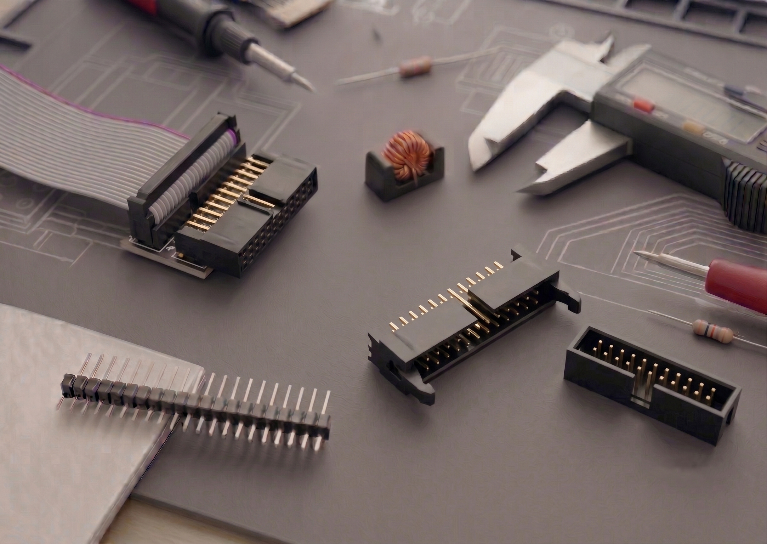
A box header connector typically consists of a high-temperature plastic housing pre-assembled with neatly arranged square contact pins. Compared to standard un-shrouded pin headers, a box header features a full four-sided plastic shroud surrounding the pins. This design offers crucial engineering benefits in hardware layout.
(I) Physical Protection and Keying Mechanisms
- Functionality of the Four-Sided Shroud
(1) The shroud effectively prevents the mating cable socket from being inserted incorrectly, misaligned, or shifted during mating.
(2) During physical handling and assembly, the outer shroud protects the delicate internal metal pins from being bent or broken by external forces.
- The Center Keying Slot Principle
(1) The plastic shroud of a box header typically features a localized cutout or recess in the center, known as a keying slot.
(2) This slot must mate with a corresponding polarization bump on the ribbon cable socket (IDC Socket), achieving a physical keying mechanism at the hardware level.
- Industrial Material Selection
(1) To withstand the extreme temperatures of SMT reflow or DIP wave soldering, the housing is molded from flame-retardant PBT or high-temperature nylon/LCP.
(2) The internal electrical contacts are made of brass, finished with precise gold or tin plating to minimize contact resistance.
II. Technical Specifications and Parameter Dimensions of Box Headers
When executing PCB routing (Layout) and component procurement selection, engineers must verify several critical electrical and physical parameters:
(I) Physical Dimensions and Mounting Orientations
- Pitch Classifications
(1) 2.54mm: The most standard and widespread specification, heavily used in legacy industrial control boards.
(2) 2.0mm: A mid-range specification balancing board-space savings with structural pin strength.
(3) 1.27mm: An ultra-fine pitch option specifically designed for modern high-density, low-profile electronic assemblies.
- Mounting Types
(1) Through-Hole (DIP / Straight): The pins penetrate through the PCB plated holes, offering the highest mechanical anchoring strength.
(2) Right-Angle (90-Degree): The pins are bent horizontally, making it ideal for side-entry cable routing where vertical clearance is limited.
(3) Surface Mount (SMT): Optimized for automated Pick-and-Place production lines, eliminating the need for through-hole soldering and saving bottom-layer board routing space.
(II) Electrical and Pin Configurations
|
Parameter |
Common Specifications and Electrical Characteristics |
|
Standard Pin Counts (Pins) |
6P, 8P, 10P, 14P, 16P, 20P, 26P, 30P, 34P, 40P, 50P, 64P |
|
Current Rating (Current) |
Generally ranges from 1A to 3A per pin (depending on pitch and pin gauge) |
|
Dielectric Withstanding (Voltage) |
Standard electrical rating sits at AC 500V / 1 minute |
|
Insulator Height (Height) |
Categorized into standard profiles and low-profile variants based on PCB vertical spacing |
III. Core Differences Between Box Headers and Ejector Headers
Beginners and procurement professionals frequently confuse these two connector families. Their primary differences lie in the mechanical locking mechanism and physical footprint:
(I) Mechanical Characteristics of Box Headers
- Structural Footprint: Compact design completely lacking integrated locking latches or ears on either side.
- Retention Method: Relies entirely on the friction between the plastic walls of the male header and female socket, making it suitable for space-constrained environments with minimal mechanical vibration.
(II) Mechanical Characteristics of Ejector Headers
- Structural Footprint: Considerably larger footprint featuring mechanical "long-latch" or "short-latch" locking ears on both sides.
- Retention Method: The latches automatically lock into the socket upon insertion; when unmating, pushing the ears outward automatically ejects the cable socket. This is ideal for high-vibration applications or environments requiring frequent mating cycles and ultra-high connection integrity.
IV. Typical Application Scenarios for Box Header Connectors
(I) Signal Bridges Between Internal Printed Circuit Boards
- Ribbon Cables and Parallel Data Transmission
(1) This is the most common use case, where the header works alongside flat IDC ribbon cables to transfer parallel signals between separate PCBs.
(2) Typical examples include interconnecting main control boards with display panels (LCD/OLED) or handling parallel bus communication between a motherboard and peripheral daughterboards.
(II) Programming and Debug Interfaces
- Embedded Hardware Standards
(1) JTAG / SWD Interfaces: The output stages of many hardware debuggers (such as industry-standard J-Link debug probes) utilize 2.54mm or 2.0mm box header ports.
(2) ISP Download Ports: Extensively used for in-circuit serial firmware flashing on AVR, MCU, or STM32 architectures.
(III) Industrial Control, Automation, and Modular Equipment
- Mitigating Assembly Line Errors
(1) Thanks to its excellent physical keying properties, integrating box headers into complex industrial equipment significantly reduces the risk of manual assembly errors by line operators.
(2) For modular instrumentation systems requiring field swappable sensor sub-assemblies, box headers offer an economical, standardized interconnect architecture.
V. Professional Selection Guide and Design for Manufacturability (DFM) Insights
-
Extreme Space-Constrained Layouts: When executing ultra-high density PCB routing, prioritize 1.27mm pitch or SMT-type box headers, and verify that there is enough flat surface clearance on the top for pick-and-place vacuum nozzles.
-
High-Vibration and Rugged Environments: If the final device will be installed in moving vehicles, automotive systems, or heavy industrial machinery, consider adding potting compound/epoxy reinforcement to the mated connector or upgrade to a latched ejector header.
-
Keying Priority Rules: When sourcing pre-assembled ribbon cables, procurement teams must ensure that the mating IDC sockets have the corresponding polarization keying bump to take advantage of the box header's anti-reverse cutout.
VI. Professional Technical Q&A: Box Header Practical Insights
Q1: What must engineers look out for when using box headers in an SMT assembly line?
A: Engineers must ensure that the box header comes with an integrated removable pick-and-place pad or possesses an adequately flat top surface for automated vacuum nozzle suction. Furthermore, the plastic housing material must be rated to survive a lead-free reflow profile peaking at 260°C (such as halogen-free LCP or high-temperature nylon) to prevent warping or melting.
Q2: What are the main performance trade-offs between 2.54mm and 1.27mm pitch box headers?
A: Shrinking the pitch reduces the physical dimensions of the pins, which subsequently lowers their current-carrying capacity. While a standard 2.54mm pin can reliably carry up to 3A, a 1.27mm pitch pin may require derating down to approximately 1A. Engineers must perform proper thermal derating calculations depending on whether the header pins carry power rails or pure IO logic signals.
Q3: Can a box header completely replace an un-shrouded pin header in all designs?
A: Although box headers add structural protection and polarization safety, they occupy a larger physical envelope and carry a higher unit cost. For consumer electronics with extreme Z-height constraints or tight bill-of-materials (BOM) budgets, un-shrouded open pin headers remain irreplaceable.
VII. Conclusion
With its low manufacturing cost, dependable keying reliability, and space-saving advantages, the box header stands as an indispensable signal bridge in modern electronics. Whether working on a prototype, a student project, or a rugged industrial product, the box header remains the most reliable, field-tested option whenever multi-wire parallel data bus layouts are required.